
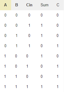
A combinational circuit can hold an n number of inputs and m number of outputs. The Sum out Sout of a full adder is the XOR of input operand bits A B and the Carry in Cin bit.

Binary Adder And Binary Addition Using Ex Or Gates
4-Bit Full Adder using 74LS83.

. Full Adder Truth Table - 17 images - lec20 half adder full adder truth table logic circuit combinational circuit adder circuits notesformsc full subtractor. Answer 1 of 3. SoC Design LabSoC Design Lab.
On similar grounds an IC has been developed which has already implemented 4-bit full adder logic in it. But I must warn you it is going to be large because there are so. But in Full Adder Circuit we can add carry in bit along with the two binary numbers.
We just have to feed 4 bit 2 numbers at input and power. 4 Bit Binary Adder Truth Table - 17 images - digital logic design 2 design a 4 bit grey to binary code converter full adder truth table and logic diagram decoration full adder. The 1st full adder includes a control line as one of its direct inputs input carry Cin.
Hanbat Hanbat National National University University 4-Bit Adder-Subtractor4-Bit Adder-Subtractor Gookyi Dennis A. You are unlikely to find full truth table of a 4-bit adder circuit. Through this article on Adders learn about the full adder half adder Binary Parallel.
And you look up carry lookahead using Google if you dont want to wait for the ripple-carry. If you need it very much you have to generate it. 4 Bit Ripple Carry Adder Vhdl Code Coding Ripple Carry On.
After full adder becomes activated it comes into operation. You make a truth table for a 1-bit adder and then make four of them. As a result the operation of subtraction is carried out.
Full Adder is the circuit that consists of two EX-OR gates two AND gates and one OR gate. Truth table and schematic of a 1 bit Full adder is shown below. Working Of 4-bit Ripple Carry Adder- Let-The two 4-bit numbers are 0101 A 3 A 2 A 1 A 0 and.
Explain Half Adder And Full Adder With Truth Table Goo Gl Y9j0jj Electrical Electronics Binary Number Computer Architecture. Also Read-Full Adder Working. A 16 bit CLA adder can be constructed by cascading four 4 bit adders with two extra gate delays while a 32 bit CLA adder is formed when two 16 bit adders are cascaded to.
Solved Write A Test Bench Program For 4 Bit Full Adder Chegg Com

Welcome To Real Digital
Binary Arithmetic Circuits

2 Bit Full Adder A Schematic Of An N Bit Full Adder Constructed From Download Scientific Diagram

Digital Logic Full Adder Using Dec 2 4 Electrical Engineering Stack Exchange
How To Display The Result Of 4 Bit Full Adder On 2 7 Segments Using Logic Gates Quora
How To Make A Truth Table Of A 4 Bit Adder Circuit Quora

Adders And Subtractors Digital Circuits 3 Combinational Circuits Adafruit Learning System
2

The Truth Table Of 1 Bit Full Adder Download Scientific Diagram

4 Bit Parallel Adder Using Full Adders Youtube
2 Bit Full Adder A Schematic Of An N Bit Full Adder Constructed From Download Scientific Diagram
How To Design A Four Bit Adder Subtractor Circuit Ee Vibes

Binary To 7 Segment Screen Encoder All About Circuits
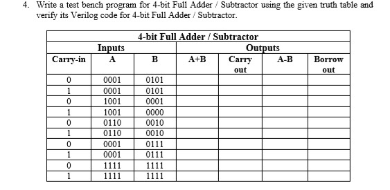
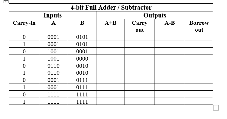
Solved 4 Write A Test Bench Program For 4 Bit Full Adder Chegg Com
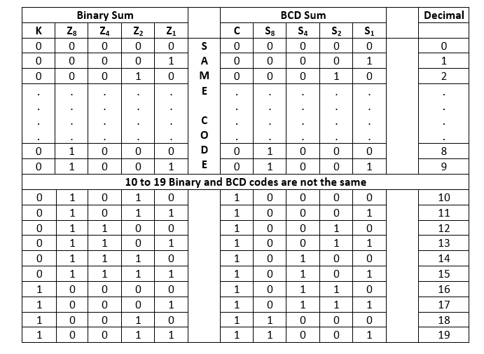
Decimal Or Bcd Adder Javatpoint
Part 2 Think Logically Diyode Magazine

Digital Circuits 4 4 Bit Adder Youtube
Parallel Adder 4 Bit Electronics Hub


